
The phased cutover approach breaks the track into small pieces and each piece is cutover one section at a time.

Figure 1 – Phased Cutover
Small manageable pieces allow the CBTC solution to mature over time. When the first phase is placed into service, the Operator has a chance to observe the CBTC solution in action for the first time under passenger carrying service.
Passenger Service presents its own unique set of problems that simulated testing will not uncover. A phased approach allows bugs to surface which gives the Supplier time to fix for the next phase and the ridership is not affected along the entire line. When phase 2 is cutover, the solution has greater stability and with each passing phase, the maturity level of the CBTC solution increases.
Transition Zone
A phased approach requires a transition between the legacy conventional and CBTC system to hand a train off.
When the cutover boundary is magnified, it’s not a hard line but a buffer called the transaction zone where the conventional and CBTC worlds overlap (Figure 2). The purpose is to allow a train to enter under conventional rules and exit in CBTC mode or enter in CBTC mode and exit in conventional mode.

Figure 2 - Transition zone in a phased cutover approach
Entering The CBTC Territory
A train approaching the transition zone from the conventional side will be travelling under conventional rules. To enter the CBTC territory, the train must cross two localization beacons for the VC to gain position and determine where it is located (Figure 3).
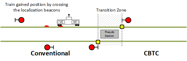
Figure 3 - Train entering the transition zone from the conventional side
The train will continue to the transition zone and stop just prior to the red signal (Figure 4). The signal indicates to the driver where to stop the train so the full length of the train is inside the transition zone; otherwise the VC will not allow the train to leave in a CBTC mode.
In the transition zone, the driver will change to a CBTC mode either ATO or ATPM. The CO will set the route from the pseudo station and the train will depart under CBTC control.
Although the signal aspect is not relevant for CBTC, the conventional side will receive the CBTC side guideway status through tie-in circuits and set the signal to a permissive aspect.

Figure 4 - Train entering and exiting the transition zone in a CBTC mode
Exiting The CBTC Territory
A similar process is followed when exiting the CBTC territory (Figure 5).
A train operating under ATO mode is routed to the pseudo station.
The train stops when it reaches the signal in the transition zone.
The train operator will change from ATO to manual mode.
The CO will call the signal and aspect will change to a permissive aspect.
The train operator will depart the pseudo station and follow convention rules
The tie in circuits will feed conventional track status information to the CBTC side allowing the train to exit the CBTC territory gracefully; the CBTC system does not leave an occupancy when the train exits the CBTC territory.

Figure 5 - CBTC train exiting the CBTC territory & entering the conventional territory
Cutover
Prior to the cutover, temporary hardware and software would be designed and installed to support the cutover (Figure 6).
Cutover cubicle for switch machines.
Tie-in circuit design to allow a train to travel from the conventional area to the CBTC area and back.
Temporary wayside, VC and ATS software that defines the pseudo station location and routes leading to the pseudo station.
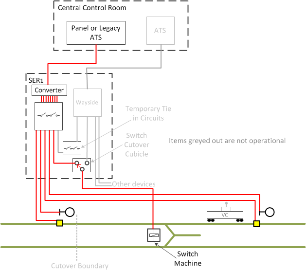
Figure 6 – Phase cutover - the day before
After the cutover the CBTC system would take over phase 1 territory:
The ATS would control the CBTC area and the panel would control the legacy area.
The wayside would bypass the relay racks in the CBTC territory and the relay logic would continue to operate in the conventional territory.
The VC would take control of the trains in the CBTC territory but in the conventional territory, the VC would be bypassed.
The data communication system (DCS) would connect the subsystems together.

Figure 7 - Phased cutover - the day after
Advantages
Small manageable areas make for an easier cutover.
Any problems that surface during passenger carrying service with the new system will affect only the small area that was cutover.
The supplier can address bugs that surface and the CBTC solution matures with each cutover phase.
Disadvantages
Temporary hardware (tie-in circuits) is required to support the transition zone.
Temporary AC, ATS and VC software (pseudo station, routes, interface with tie-in circuits) is required to support the transition zone.
Two COs, one for the legacy panel and one for the ATS, must work in close coordination to handover a train from the conventional to the CBTC side and vice versa.